Welcome to my Blog. Over the next couple of years i will be updating and showing you all the progress of my AK 427 Cobra build. You will be able to track my progress building a lightweight sportscar with monster V8 power, stunning good looks and alot of hard work and determination.
Its been a long time since I last updated the blog on my Cobra and
everything Cobra related, and this has mostly been because i have been
hooning around the countryside in it like Toad of Toad Hall. However I
thought it was time to give you all an update and show/tell you about some of the
creases I'm ironing out... or at least trying to.
The images opposite are from the NE1 motor show that was held in the centre of Newcastle in 2016. This was the second year for the show, the first year back in 2015 had all the display cars on the show with no barriers or restrictions for the public and with a change of plan from the organisers the 2016 show had the cars fenced off from the foot fall. This made it much more acceptable for me as the narrow city street and massive footfall of traffic allowed me to keep people back from my paint. I love to display my car but i get seriously infuriated by the people that show little or no respect for other peoples property and can cause damage by not being careful. The 2016 show was a great success and you can find lots of videos on Youtube if you look... I'm in a fair few of them. The show ends on the Sunday when all the cars parade down the street and merge with the general traffic coming along from the one way system. The crowd that gather are very impressive and its hard not to give them a show in the style of some burnouts, however in my case its normally "pride before a fall" so just lots of noise from me and aggressive accelerating onto the main road.
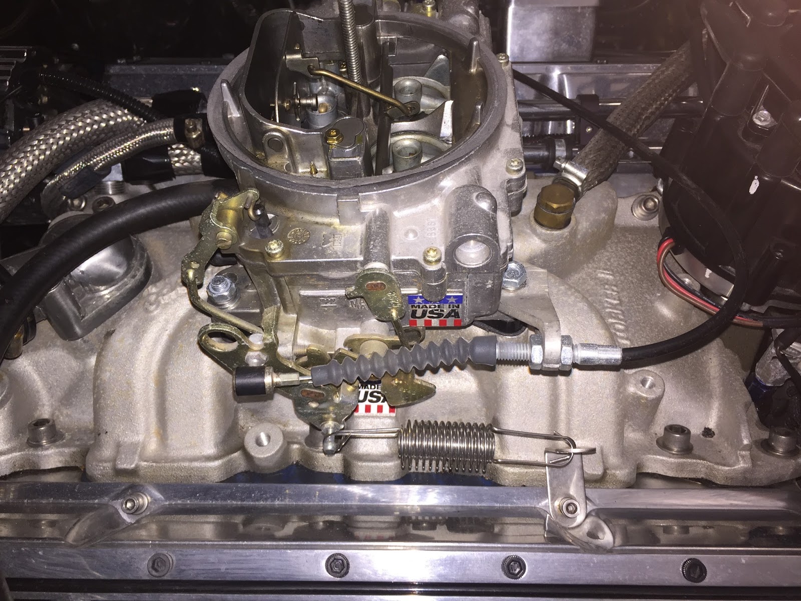
My car has spent the last few months hiding away from the world in the garage, but as soon as Christmas and New year was past it was fairly obvious that we were not going to get a significant snow fall this year so i started making a list of jobs that i would like to sort out on the Cobra. My list hadn't started getting very long when i started her up after a month of being idle and my throttle cable started jamming, and not returning fully. The cable was originally one purchased through ebay that was marketed towards a Dax Cobra if i remember correctly. And upon closer inspection (see image) you can see how badly aligned the throttle cable is in relation to the fulcrum.
This sure as hell wasn't helping the issue, and I'm almost ashamed to be showing the images of the cable and the crude setup that i had for a throttle linkage and brackets. Something had to be done to help straighten the run out and stop the cable from sticking. After a fair bit of Internet trawling and lots of google image searches, I eventually found a bracket that looked as if it could work and help with this problem. The price was also good as these fancy throttle brackets from America are normally in excess of £100 when you cost in import duty etc... So with mine just £28 of ebay it was worth a pun. The bracket arrived and it looked to be very good really. It has also come from overseas.... but this time from the other side of the globe from China.
The bracket consists of a double spring return pin, along with the throttle cable positioned in alignment with the carburettor. When I was looking at the dimensions of the bracket on the website it was compatible with my Edelbrock so hence why i placed the order. I also ordered a new throttle cable just to be on the safe side, i didn't want to risk the cable i have not being compatible and needing replacing also, so a universal unit was purchased for £12 (hardly breaking the bank even if i don't use it)
Its not easily visible in the image here but the bracket wasn't as good as I first thought. When the air filter was off and the old throttle cable bracket and ancillaries removed I could see I was going to have some clearance issues with the carbs linkages and the bracket. The mechanics of the carb need to be able to move freely without hitting or touching any part of the bracket which could cause it to stick open along with allowing it to fully shut off and open on demand without restriction. So £28 out of pocket it was time to start trimming.
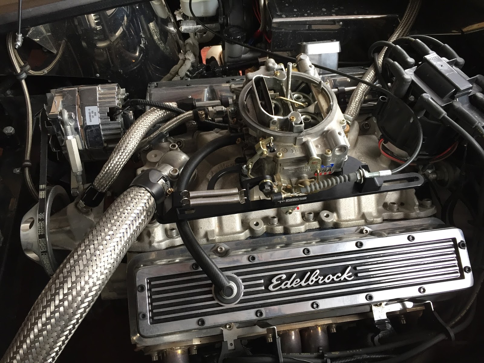
I measured and masked up a section of the bracket that needed to be removed and then spent a good period of time filing and grinding away with various files and drum sanders, until i was happy with the finish and fitting. You don't need loads of clearance between the carb and the bracket as when the bracket is in position and bolted down it is fixed and doesn't have any flex in it. But still enough clearance is needed to allow the throttle to full sweep from open to closed without the risk of any voiding. I spent a good amount of time getting this right, mostly because my hand files have seen better days and I bought cheap ass drum sanders for my dremmel that disintegrate at only 1 revolutions per hour... lesson learnt, buy cheap, buy twice.
So with the trimming of the bracket sorted you can see that it now has sufficient room to move and not get caught or jammed, so i started fitting the return spring bracket and throttle cable section. The return springs are now fitted to the linkage above the pivot point, as opposed to before when they were pulling on the same side as the cable from below. I have done a little reading about how this can cause damage over time in the body of the carb and give excessive play within the setup and render it scrap. Granted i think this would take a fair few years to occur but, belt and braces as with most things on this build.
So with everything back together i was able to use my existing throttle cable with the new bracket with some minor adjustment to the fitting. I was conscious that i should be setting the amount of travel with in the cable to give full throttle and also full closure when released. With some fine tuning I have managed to get my accelerator pedal to bottom out on the floor at roughly the same time as fully open carb. This will hopefully allow some longevity on the cable as if it was stopping on the carb linkage then the cable could get put under further pressure from my right foot and possibly snap..... which i don't really want.
All back together now and it was time for a test run, the throttle is nice and responsive and returns quickly when off the pedal. A slightly different feel to what I had previously but these new springs are a greater force then before so a little heavier on the throttle foot is needed, by no means bad just different to what I was used to.
I'm sure your familiar with the saying "two steps forward, one step back"...... Well that's what I've just bloody done. I have gone and solved a problem quickly and effectively but as a knock on effect i have created another....... the air filter.
When I put the air cleaner back on it was fine but because I have now technical spaced the throttle up slightly from its previous position, the bottom of the air filter voids with the swinging of the throttle return cable and only gives about an inch of movement... bugger.
I fitted the air cleaner in its position and rolled up a bit of blue tac, with this on the highest point of the air filter and the bonnet closed the now squashed bit of blue tac should give me a measurement of how much room i have to play with to raise the air filter up.... not much just under 1"
I have now placed an order for a spacer that measures 3/4" and fingers crossed this will give me the clearance I now need. If not its back to the drawing board with the whole bloody thing.
So another update soon..... probably next week when its been delivered and in turn create another problem by fitting that. ha ha
Well i have been enjoying Cobra ownership for a good few months now and if you have been reading or following this blog with the intention of building a car then go and get the bits ordered ASAP. The satisfaction of just cruising along with the wind in your hair and the looks on peoples faces as you go past. I have always driven cars that have seeked attention but none so much as this, just today i was having an enjoyable drive about the local countryside and as i was heading back home through a little village i had kids on bikes shouting "Nice car mate!!" and "Wow look at that car!!" along with thumbs up from people on the street and one bloke who wanted to shake my hand at the traffic lights and compliment me on the car. Whilst this is extremal vain to get a buzz from this kind of reaction its just the satisfaction that i built this car myself and that it makes other people smile and grin when I'm out and about in it.
Today's trip out was just a little tootle about to get some nice pictures really. Since i have finished the car all the images i have are basically at my house or around the garage, but none with any set scene or backdrop. So off for a little mystery tour around to see what i could find. I headed away from Newcastle and into Durham and soon found myself heading past some huge wind turbines, so i though i would get as close to them as possible. I soon found myself heading down a narrow country track with the wind turbines in the field next to me, then as i got closer to the gated entrance i could see a nice stone wall running up the edge with a gravel track that was not to aggressive for the car to go over. The entrance to the field was just a farmers gate with no lock or warning sings, so i just hopped out opened the gate and slowly drove into the field and park in a suitable position.
The sun was out and the wind was up a fair bit which kept blowing over great big dark clouds, but overall it was warm and pleasant enough to get some nice pictures of the car. The wind turbines were making a terrific noise as they were spinning around and whilst many of these are visible from my house i wouldn't want to live to close to any as the noise would be very annoying for long periods. However out came the camera and i spent some good time happily snapping away and taking some nice shots of my pride and joy.
My next planned photo shoot is to try to get down on the quayside in Newcastle early one morning, before any traffic or events. Then i want to find a photo position with the car and the Tyne bridge in the background and one with the Millennium bridge also. I have been planning some spots with the aid of google street view and i think with a minor infringement of parking fully on the pavement i think i have a good position in mind. I intend to do a dry run in the daily drive just to sus out things like drop kerbs and places to park up if needed. I cant see it causing any problems, however we live in a world full of jobsworths and big brother CCTV, and as mentioned earlier its not exactly a subtle discreet car to drive about in.
To leave you this update i will just remind you that these cars are never really finished. Maintenance and modifications are always needed. As i was driving back home after leaving the field (and shutting the gate again) i adjusted my drivers sun visor and it came clean off in my hand... bugger!!
It had stripped the threads in to the windscreen frame so this will take some careful attention to rectify. Due to the glass being so close in the frame and the risk of cracking the glass if the thread penetrates to much. So it looks like some more quality time in the garage is needed.
You wait months for an update then two come along at once, in the space of a week.... sorry thats just how it is.
I will start this one with what i have been up to this bank holiday weekend. This weekend saw the Stoneleigh kit car show, and i didn't go. The weather on the Sunday was dire and the 4 hour drive with no roof was just no doing it for me. I looked into getting a train but i would have had to remortgage my house and set off a week prior, according to the ticket website. So time with the family it was, with a some quality time in the garage during these lovely light evenings. These are my most favorite times in the garage, i always get something productive done and some quality soul and blues from the local radio.
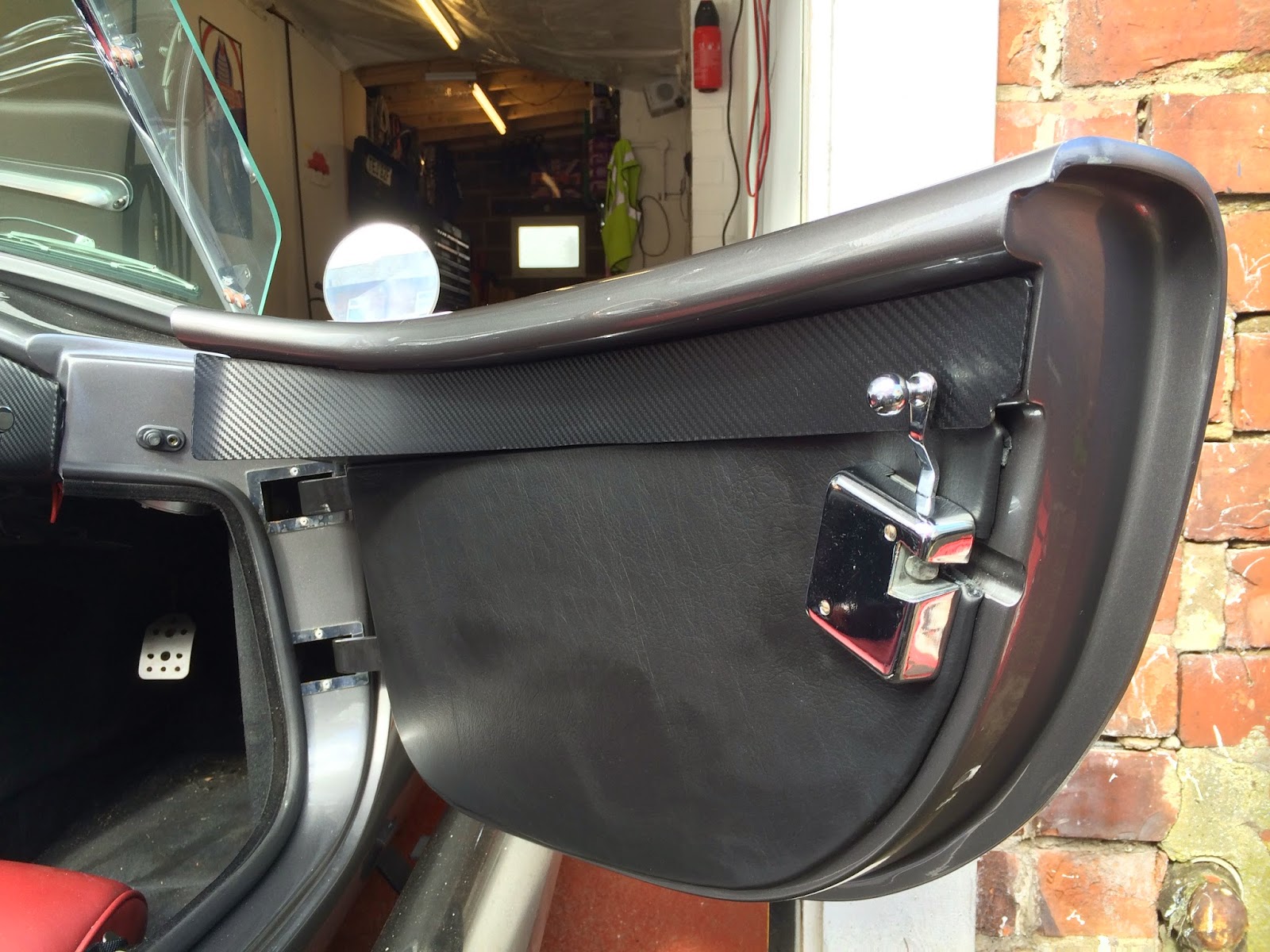
So the last few evenings have been well spent in the garage with my first task to finish the carbon fiber panels following the dash along the top of the doors.
These are really easy to make up. First i made a crude cardboard template and checked that it would not void anything like the door catches or door seals, then once i was happy with that a second neater lined version was transfered onto 2mm acrylic plastic. I used plastic as it wont absorb water and go out of shape if it gets wet and it will also wrap in vinyl easily. The plastic was actually cut from a section of flat channel trucking that is used for the likes of cooker hood extractors and bathroom fans. Either way its cheap as chips and cuts easy without shattering.
Once that was cut out and trimmed to fit round the door lock, i just wrapped it in the same carbon fiber vinyl that i covered the dash in. Attention to detail also here making sure the direction of the carbon effect twill was continued along the door card panel also. If it went in the opposite direction it would have looked very odd, to me anyway.
The then finished door strip is held in place simply by using lots of self adhesive pads stuck all the way along. I did have to use a heat gun on the broad end slightly on both the panels just to add a little curve in order for it to sit against the dash nicely, but over all i'm pleased with how they look and fit. I had always intended to fit these since i did the dash in the vinyl, and its not something i'v seen on many other Cobras, so another little custom finish for my car.
Next on the niggle list was the rear mounts for the
harnesses... or at least i think this is what it is. When i'm driving on rough road surfaces i'm getting the occasional but irritating rattle from what i now think is the rear harness mounts. At first i though i had an issue with the passenger door latch as it wasn't as easy or smooth as the driver side so i spent some time fettling with that not long back. However on my last drive out i was still getting irritated by the noise, so in a desperate attempt to solve the noise i'm going to start to insulate and secure anything and everything i can. The rattle only seems to come from the passenger side and when driving so i presume its when their is no tension on the belt fixings that the metal knocks and chatters..... so solution time, i hope!!!
I took loads of strips of the same self adhesive pads that i used for the door panels and then used them to wrap the eye bolts that the harnesses clip to. My theory is that this will stop the metal on metal contact so should help stop any chatter coming from them, however i haven't been out for another drive yet so i'm not 100% sure this has worked, or if this is even the source of the noise, it might still be the passenger door lock. I will need to take a drive out with a passenger who can hold the door and listen out at the same time if the noise persists.
until the next update enjoy the spring weather.... forecast heavy rain for the next week, Joy!!!
Well where do i start this little update? so much to say and so much has changed i have learnt allot and nearly lost allot. Since getting legal and having a little fun in the piss poor weather through the back end of the winter i was seriously looking forward to my first little north east Cobra meet. The plan for the day was to drive up to Ian's in Gosforth then off over to Whitley Bay to meet a new face on the local scene John, who has a Pilgrim Sumo. Then a drive over to Johns unit where he keeps the car and then over towards James in Bishop Auckland via the Tyne tunnel..... yes massive excitement for though the tunnel in these monsters, and this didn't disappoint.
So the day started well and i had a great drive over to Ians house (via a petrol station) where after a little bit of banter and general Cobra excitement we were soon on our way off to the coast to pick up John. It is one of the best things about living where i live, i can travel 30 minuets in one direction and be dipping my toes in the clear water of Tynemouth and Whitley Bay. And yet 30 minuets in the other direction sees me in the depths of the stunning rural countryside of Northumberland.
John was soon strapped into his shotgun seat in Ians Pilgrim and we were heading for the tunnel, by this point the nerves of listening to every single noise from my car and the fear that something was about to go wrong were fading and i was seriously starting to have fun, i was very grateful Ian had a spare of gloves as it was flippin cold and i'm not as hardy as i thought i was.
The blast through the tunnel was epic, the noise from the cars was superb and i didn't see anyone without a bloody big smile on their face as we blasted through at a eye watering top speed of 40 Mph. The speed limit is in place for safety (naturally). Some people have been saying that its to generate revenue and stop anyone in a flipping loud Cobra having any fun..... i could neither agree or disagree.
After the excitement of the tunnel we were soon at Johns unit and were we all soon looking over his Cobra. It had been off the road for a few years now and was in the process of a mild restoration to restore to its former glory. After a few hours and a couple of cups of coffee we were on our way towards James in Bishop Auckland.
James has an early Dax kit which is undergoing a full restoration and re spray and he is another flash sod with a bloody great garage complete with inspection pit and space!!! i'm starting to think i was at the back of the que when God was handing out garages...ha ha.
So after another few hours and more coffee, this time with cake and biscuits (John take note!! he he) we were starting to make our way home. Ian was taking John back towards Whitley Bay (via the tunnel again) and i decided to head back home up through Tow Law (a very rural and isolated little town) with some stunning views across the countryside, in fact i feel this is my new favorite road as it has bends and twists for fun along with great stretches of clear straight for some powerful overtaking maneuvers. And its a great place to set off car alarms as you drive through with the reverb and deep burble from the giant side pipes on the car (i think i have found a new game to play!!) Heading home just out of Tow Law it was at this point fate was against me and the start of the deep dark depression began.
I was not more than a few miles from home when a rattle suddenly appeared from no where. After a quick shift into neutral and whilst costing along and blipping the throttle to see if it was picking up with the revs it was to late, i had to select a drive gear again in order to get to a safe place off the road and although costing along at about 60 mph i went strait into 5th gear and started to indicate left. The rattle by this point i had established was picking up with the revs and as soon as i selected 5th gear and start to pick up the drive again their was a "PING!!" and the rattle stopped.
I had a gut feeling what the problem was as a couple of week prior i had gone for a short drive up to work and back, and the return journey i had a rocker pinch bolt work its way back slightly and allow the tappet to become rather loud. This is not uncommon for an engine which hasn't seen a serious operating temprature for a good few years and not forgetting this had only just been rebuilt prior to me taking delivery, so a potential of an air bubble in the hydraulic lifter was high. Either way when this had happened i had done some digging about on the internet and had been checking how to set the "valve lash" this is simply a half turn of the pinch bolt as soon as you feel it start to grip/resist the push rod as you rotate it through your finger. The important factor is weather your lifter is primed with oil or slack when you set this pre load.... something i was unaware of completely. Because my lifter was primed with oil when the tappet had worked its way loose i must have set the pre load to high "excessive pre load"which is dangerous to the engine as it can hang a valve open to long and allow the piston to smash into it and basically destroy itself.
Anyway i was now about to pull over and check things over, i had oil pressure and although the engine sounded rough it was running (all be it on 7 cylinders) after some quick though and a gut feeling it was the push rod i decided to get back home slowly and watching all the gauges like a hawk for any signs of oil pressure loss or overheat. I was back in the safety of my own garage within 5-10 minuets and i was to depressed to even look at anything, such a great day out (only 240 miles since IVA pass) and my first real trip out in the car and this had happened.
So after a few days of sulking and the frustration that the good weather was on its way and i was without my car was enough to nearly see me swinging from the joists by a length of rope. I had in this time spoken with Wendi and Jon at AK and i was at first a little pissed off with the whole situation. My engine was purchased through a company no longer trading so my warranty was worth shit, however the guy who physically built my engine (Jez from Custom Power and Paint) for the company i purchased through is a very well respected and good V8 engine builder. Jon advised me to contact him and take his advice regarding the issue but either way it would be time to start pulling parts to bits. I had removed removed the valve cover already and it was obvious that i was missing a push rod from the inlet port on cylinder number 1. At this point i was not sure what exactly the problem was, just an idea and diagnostic from my own understanding that the engine had basically eaten a push rod, which cant be good news as i had no idea where the rod had gone.
i had been trying to contact Jez it had been a good few days and still no return call, just an answer machine so i contacted Jon again at AK who said he was on holiday for a few weeks and it was best that i pulled the distributer and inlet manifold myself to get a better look myself. After a couple of days i went to the garage and started the painful strip down of everything on the top. Off with the carb and all the throttle cables etc... then off with the distributor and removal of the inlet manifold. This was all new ground for me on this engine as previously my experience of any V8 strip down was of the old Rover V8 from a SD1... the basics are very similar mind.
So when the inlet was off i was confronted with a very knackerd push rod on the inlet valve with the top third of it laying in the valley of the block. So here we have the "Ping" noise and the sudden stop of the rattle when it first happened. Next on the list was to check for valve damage, and damage to the lobes on the cam. The lifter itself had jumped right up in the block but not fully out of its bore and apart from that it all looked normal. So now what about valve damage? In order to check this i would have to run a pressure test on the effected cylinder and compare it to a couple of others to see if a large variance was present, In order for me to achieve this i had to order a pressure testing gauge and some other bits in preparation to the rebuild.
After a few days parts and tools started to arrive and i had also had a return call from Jez. This was really reassuring as he certainly knows his onions when it comes to SBC V8 blocks, and not once was he surprised annoyed with my probably stupid terminology and crude descriptions. Remember Jez had no legal obligation to help me and could have quite easily told me to naff off, but luckily he is just as everyone had said he is, a genuine guy who was happy to help. He agreed to send me some new gaskets for the inlet and some new poly lock rocker bolts and a new set of push rods and true to his word after the Easter break i was in a position to start checking the pressure and if ok starting the rebuild.
The pressure result was such a relief as it showed a health 160psi and a cylinder on the offside bank showed an equally healthy 155 psi. These were cold crank readings with a low on juice battery, but both within tolerance so i slept well that night confident that valve damage was not going to be an issue. A few days later when life allowed time, i was back in the garage starting the rebuild process with the aid of loads of advice from Jez and loads of videos on Youtube form Summit racing, the basic strip down and hand rotation of the engine is fairly easy and logical when you look at the physicality's of it. I had lots of bolts and washers soaking in white spirits for a few days and i took the time to clean all the inlet manifold and head surfaces with spirits also, whilst the valley of the block was covered and the ports shoved full with clean rag. This is to stop any dirt ingress that could cause any damage when start up happens again. The oil was also drained from the sump and the filter replaced for safety, after all a push rod snapping in half could have left a small shard of metal that could damage the engine. The push rod did have a fairly clean break when matched up together but i wasn't taking any risk for the sake of new oil and filter. When the engine was in this stripped down state and the spark plugs removed Jez advised to rotate the engine by hand a 1/4 turn every 3-4 hours. This is to bleed down all the pressure from the lifters and drain the oil from them, and thus when setting the preload it will be to the correct tolerance... and not to high/low.
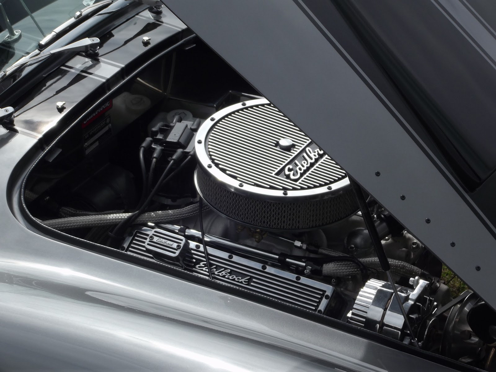
So after a good few days of a slow and steady rebuild with lots of cleaning of parts and allowing time for the high temprature silicon to cure on the gaskets and valley seals, i was getting ready to start the engine again. One other part to this learning curve was setting the timing for the initial start and the total advance timing when the engine was up to operating temp. Jez advised an initial timing set to about 15 degrees advance and a total advance to 36 degrees. I purchased an advance dial in timing light which makes setting the timing child's play. You just set the number of degrees advance required with the rotary dial on the gun and then align the TDC mark on the balancer to the pointer... really easy stuff and very effective. Again i watched a fair few videos on youtube first to give me the confidence first, but after having set my timing to fire on the exhaust stroke of the piston rather than the compression it fired up straight away!!! YAY!!! I had been turning the engine over a bit first to build up the oil pressure and then i connected the live to the HEI distributor, then broom broom time again. As you can see in the last image also that when i went to the extent of sorting all this out i was buggered if i was putting on those nasty looking valve covers and air cleaner. So a week prior i had remembered the pin for my credit card and did the job properly with these Edelbrock Elite valve covers and air cleaner, so much nicer and suit the style of the car and color scheme better. Tommy was a happy boy again.
So now back up and running i have clocked up another 100 miles last weekend just taking it easy and having some nice driving through the country side in the sun...... yep sun!! we do get it occasionally. Granted that has since disappeared and been replaced with snow on the 28th of April however it wont last long and im looking forward to some more fun in the Cobra.
Weekend coming sees the Stoneleigh Kit car Show, i still don't know if i'm going this year as i have no garage to keep the car in over night and the weather forecast look dire all weekend. I might jump on a train and have a quite skulk about, but we shall see.
Next update wont be long, with some fine tuning to my Cobra in the fashion of heat protection.
Lots to cover in this update, sorry its taken so long but what with Christmas and shit weather motivation has been hard to find... yes even after getting legal!! Driving opportunity's have been very hard to find along with windows of dry non raining days without risk of getting wet, however a little bit of bling to start us off.
I was never intending to keep the standard BMW indicator stalks with big black plastic ends, so after a lot of hunting around the Internet i found a German company that make and supply these gorgeous stalk ends made from solid alloy and finished to a high polish. The also have three grooves in the end which three little o-rings sit in, that just look bloody superb to me and seriously high end.... as opposed to old grubby black plastic.
They are held in place with a subtle little grub screw that can not be seen if positioned correctly on the stalk. Fitting them was child's play as the left stalk (indicator) only has 4 positions, up and down to indicate left or right and forward/back for full beam or flash. The right hand stalk (wipers) does have additional positions that are redundant on the AK loom as these cars have no rear wiper or washer facility however stalk still moves to these positions. The only one causing an issue for the fitment of these ends is the push in (stalk in towards the column) for the rear wash. Once i had pulled off the original stalk end i just simply cut the two wires, insulated them and pushed them back into the stalk.... then on with the new chrome end and grub screw tight....... sorted!! so sorted in fact that i posted a thread on the Cobraclub forum which started a copy cat effect with most AK owners ordering a pair from Germany. Maybe i should have been on commission??
Next on my list for adding some personal touches to my car was bonnet rivets. I have always adored the little rivets on Cobras which hold the bonnet skin, to the frame and also around the air scoop. But with my body being fibreglass and the scoop not in the slightest looking anyway near original, it was time to do what i wanted and what in my opinion looks good. Lots of different layout can be found easily, varying slightly depending on chassis number/production date. So with my car matching non of the original dimension it was just a trial and error basis with the layout. Some tips for the planning stage is to use the little paper circles from a hole punch to lay on the bonnet first before committing with rivets.
Once i was happy that i wanted to fit them i started to mark out the head positions based on one of the layouts i had found on the internet. I ended up with 1 rivet centre and 13 out from that (so 13-1-13 ) i followed the dimensions of the guide roughly for the spacing and with some masking tape over the bonnet i was able to accurately make the positions for the rivets to be fitted.
I spaced the rivets out evenly and marked each point ready for drilling into the body. The originality behind these rivets was to secure the body panel to the frame, and with my body being made from fibreglass this is a 100% vanity modification. Also with the bonnet being one piece i didn't want to drill all the way through and have to see all the rivet butts on the underside. Along with the stress each rivet would cause to each area and hazing to the paint i decided on a different approach.
With my car colour theme being black and grey i wanted to continue with a colour that didn't look odd or out out of place against the bonnet so i opted for some black bodied rivets which i got from CBS. These had to have the pins removed then the body cut down as so that they could just be bonded into shallow holes drilled in the bonnet. I chose to bond them in rather than actually rivet them in because of the damage they would do to the paint and having to see the compressed rivet body from the underside of the bonnet.... and don't forget this is purely a cosmetic modification.
So once all the rivets were cut down and the pins pushed out i checked all the markings again for spacing and to make sure it looked symmetrical against the stripes and body lines. Then with a 5mm drill bit i slowly put a shallow hole into each mark to allow the rivet to sit in place with the head sitting flush on the body. I didn't drill all the way through the bonnet just deep enough for each rivet to sit nicely, about 3mm. Once all the holes were done i mixed a small bit of epoxy and bonded each rivet head into place after removing the masking tape and after a few hours to cure they looked the dogs bollocks against the colour and body lines. I'm glad i did this as once you have drilled your bonnet you can hardly change your mind after. By this point i was decided not to attempt to put any around the scoop, they do look good on the original cars but with my scoop being four times the size i think it would look odd and a little over the top.... less is more.
I decided against following the marking guide to the letter and having the corner rivet following the curve of the bonnet so that the first rivet parallel with the stripe is closer to the corner one (see 12-1-12 pattern image above) When i planned this out in the initial marking and hole punch circles, it just looked odd and not correct to the body lines. So as said previously i just went with what i thought looked better, and considering its my car that should be enough justification surely?
Next up... Christmas time. After recouping some disposable cash over the festive season i decided to start some research into side screens or wind wings. With the 111 miles i have clocked up to date one thing that was uncomfortable was the wind buffering when you get up to a good speed. In an attempt to help this i have invested in some glass wind wings and sun visors. I have been reading on the forums regarding glass wings that just suddenly explode when driving along or when just shutting the door the shock can shatter the glass. So with some careful thought into the pros and cons of glass over plastic (acrylic) i went with glass. Granted if when driving along they get hit by a stone, bird, pedestrian or cyclist they may shatter... but no more so than if it/they was to hit the windscreen. The glass is i suppose at eye level and could do some damage if the worst happens..... but keeping it positive i would just end up looking like a James Bond villain with lots of little scars all over my face..... girls love scars and fast cars, win win situation!!!
The fitting of the wind wings is simple really the bolts fit through the glass with a fibre washer each side and onto the hinges which then fit directly onto the windscreen pillar, job done.
Next up was the sun visors... these were a little bitch to fit and I'm still not 100% happy that they will have any longevity to them and considering they were the best part of 150 bloody quid i should hope they will. The visor itself is smoked acrylic plastic with hinges fitted to one edge. These hinges then have a groove cut in them allowing that to then slot on to two tabs that fit to the windscreen frame. The hinges then grub screw onto these tabs and are secure the visor is held in place with the friction of the hinges... or so it should be . The problem i had was the little tabs that screw to the frame were basically shite. The screws only penetrate the screen frame by a couple of threads or else they would touch the glass in the frame and crack the screen.......that was something i didn't want to do so i was very very conscious of getting them tight but not over tight.
The passenger side was ok after a bit of fetteling with the alignment of the holes, and i found the counter sunk area to be seriously poor fit for such a basic fitting. But when fitting the drivers side it was a pigging ball ache. One side for the hinge was ok but the other was so bad that the threads of the screw could not penetrate the tab itself let alone into the screen frame. I was left with no option but to thin the mounting tab thickness to allow some of the screw threads to pass though which then allowed it to fit and grab the thread on the frame. All of this was irritating because again theses were not a cheap purchase for the car. That and the fear of cracking the windscreen when fitting... should i tighten the screw so the visor wont come clean off in my hands... or do i just leave it not as tight as i wanted in case i tighten more and crack the screen..... hmmmm???
I know all that wont make much sense to someone who hasn't fitted them before but it wasn't just a straight forward "out the packet and bolt on" situation.... but nothing on this car has been.
Lastly a fairly simple change. The fog light is now on a clear lens with a coloured bulb. I much prefer this and it looks much neater and balanced from the back. I'm playing around with a coloured bulb against an LED bulb as the red glass makes the lens look darker against the reverse light, where as the LED doesn't.... but its not as bright. So a little more messing around with that one.
Apologises for such a delay in the update after getting legal. Yes driving one of these cars is all it as expected, phenomenal power with biblical acceleration, aggressive road stance with a monster sound track. Overall a serious driving machine that tries to kill you at any moment it can if you don't show it the respect........ hurry up summer!!!!
So after my last update which was mostly finishing of the cosmetics of the interior, it was time to start prepping the car fully for IVA. I had a confirmed test date of 11th November (a day to remember surly?) so it was time to start getting serious with all the possible issues i could have. AK provide a "IVA kit" which consists of a lot of bits i didn't actually need in my case, simply because of the way i had built the car. for example part of the IVA test is to hold a numberplate sized template to the mounting area to which their must be 10mm distance around the plate. With a standard AK setup (using a traditional boot lock) you need to space the numberplate light housing up slightly to give you the clearance for the plate between the light and the boot handle. However with my cunning secret hidden boot lock i had no need to have a handle and thus no need to have to space the plate light up to fit in a number plate...... i got frigging loads of space!!
The bits i did need were in my opinion "fuck ugly" such as the delight full looking head rests...These are now an IVA requirement and this is the best way to fit them as they fit to the back of seats onto some protruding studs and just held in place with a penny washer and a few nuts..... so they "could" be removed at a later date and have no visible fixings in the top of the seat. You might also notice in the image a lovely leather spoked steering wheel.... this is to meet the requirement of the radius edge of the spokes and to ensure no jewellery or fingers can get caught in the wheel..... tick in that box please!! Also i had to botch up a gear stick without the lockout bar, as this again would have failed the test. So i nice length of thick gauge tube with a nice bend held onto the gear selector with a couple of threaded bolts.....this because a real IVA issue on the day, as the begger kept coming loose and changing gears because interesting. Also you will notice i had to do a last minute harness change... my nice custom made harnesses would have failed IVA due to the latch and the tension buckle, so an appeal for help on the cobra forum saw Pete posting me a spare set he had in his garage which he used for his IVA test..... phew!!! another tick in the box, i hope.
I spent the evening prior to the test checking everything, and I'm so glad i did. I was adjusting the rear height as i needed to brim the tank for IVA and when i stood up from the nearside with my hand on the door, it released and unlatched..... hmmm this isn't good, as part of the test is the doors to have a double latch and not to release with anything up to roughly 30kg of pressure. I only had to breath on mine for it to unlatch, so hours spent pissing around in the dark adjusting the striker and lock spacing was needed to get it set correctly. This had been fine previously but a road trip to the MOT test station on the 8th must have allowed a little movement.
So at stupid o'clock on the morning of the 11th (in the rain, dark and cold) saw myself and my mate Ian about to have the first proper journey to the test centre. My test centre was a good journey away, which had a short motorway section also so i was very grateful of Ian helping and just following me in his daily drive, just in case anything did happen. My dad was going to be the second car but him located in the midlands amongst other personal reasons he was unable to attend on the day. So with the bull firmly gripped by the horns i jumped in strapped up and hit the "GO BABY GO" button..... wow!!! what fun. I was so nervous about driving for the first time and having to be at the test centre for 8:00 meant some serious rush hour traffic was hit.
Id only gone about 5 miles down the road and i had to stop for petrol already. This is because the car must be presented with as much weight as possible so it needs to be up to overflow on the tank. However i didn't leave the petrol station before a passer buy wanted to shake my hand and say such things as "nice car mate"... so it looks like I'm going to get noticed driving this about.
Another short blat up the A1 and off just after Gosforth saw me sat in more stationary traffic, which allowed the engine temp get fairly high. However when i was moving with a good flow rate of air going in the nose it sat at a very good temperature and was perfectly acceptable. So dead on 8:00 i arrived and was swiftly parked up in the area to start the test. I met my IVA examiner (Alistair Thompson) who was a great bloke to chat with and he genuinely looked happy to be testing something different to the normal daily grind of such a job. One issue i did have was the constant stop start of the traffic and 1st to neutral had seen the bodged gear leaver work its way loose, however i was allowed to quickly unscrew the cover boot and tighten the two nuts. I was at this point a little worked up and fretting over things, however a cup of coffee calmed me down and the test began.
My IVA tester was himself also getting tested by VOSA at the time of the test for time productivity. Some suite in an office that has no idea what the job entails obviously thinks to much natter is happening and its affecting productivity... but this is not my battle so I'll just concentrate on the IVA test.
I wont go through everything with you regarding the test but it was really an enjoyable experience, the general banter between myself and the tester was good and i believe the answers that i provided were showing that i had a good understanding of what the rule was for and how to comply.
This image shows the car on the rollers to test the speedo accuracy. Whilst my speedo was within tolerance, so it could not be failed technically, it was however wrong by an unacceptable amount for me. So i will need to dig out the GPS unit again and reprogramme the speedo to give a truer reading of 70mph. This was great fun to watch and even though it wasn't a power run, like on a rolling road it was funny to see the car rolling up to 70mp but stood still. You can watch the video below.
This picture makes me giggle, because i clearly disagree with something i have just been told, or I'm telling him something that is not to my liking. haha
But you can see the car going through the brake tests in the background. Front and rear brakes all tested once with the engine running (servo assist) and again with the engine off (no servo assist) along with the park brake. The figures generated from this are then calculated to the weight of the loaded vehicle and braking efficiency is either passed or failed accordingly.
Next was onto the emissions and checking the engine was within tolerance of the CO2 and hydrocarbons. This is where the age relation of the engine is taken into account, and the evidence (official letter) was produced to verify the block. The offside was fine with no issues but the nearside needed a little fettle and tweak. My tester was more than happy to allow me to do this and after a couple of minutes i had a tick in that box also... next onto the sound test!!
The sound test is carried out by reversing out into the car park (no sound reflection of any buildings) and the engine is reved to 3/4 of its peek power in my case that was 3500rpm (on paper) and with the sound meter set at the correct distance a reading was given. Because i was sat in the car and i couldn't see the gauge i was completely in the dark as to what the reading was. My previous tests at home with Ian's sound meter saw me higher than legally allowed, so i was nervous on the outcome for this one.
Onto the final stage of the test. This was a weight check and a centralisation test of the steering, along with rear visibility out the mirrors. I had to ride shotgun for this one as i wasn't allowed to drive it myself.. just lucky he could reach the clutch as I'm fairly tall and the seat was fixed for my driving position. But again massive tick in the box for the centralisation of the steering. The tester drove in a big figure 8 shape and on a full left lock released the wheel and the car started to pull itself straight instantly along with the full right lock also!!!! another tick in the box. It was rumored on the day that we did this test twice as (even though the IVA rules state a handbrake warning light must WORK!!) the first test was done with the handbrake on....... but i couldn't comment on that. haha
So with the final stages of the test complete it was pass or fail time. I genuinely didn't have a clue as to the result... but after the tester had returned from making some calculations, he shook my hand and congratulated me!!! PASS!!!! 1st time!!!
This was superb news for me and I'm so proud that i have achieved it. The end of the road for the "building" stage and onto the "driving and making improvements" stage.... after registration.
The drive home also saw some afternoon sunshine, nice!!
This is not the end of this blog, mearly a start of the rest of cobra life. No doubt i will encounter problems along with making changes to the setup and power of the car. So keep checking back for updates every so often.


