Sunday, 14 April 2013

Flash lines....... not Gorden. (but he is alive)


  Started tackling some long overdue bodywork prep. I'm just making a start on it really, i intend to leave most of the fine tuning for the body shop, such as door/boot/bonnet gaps. However removing the flash lines from the mold is a simple task so long as you don't take too much off and then leave a flat spot. So just long a tedious work with fine abrasive paper to take the bulk of them down. Another good reason to be fitting the interior and carpet after paint is because of the dust, fibreglass and gel coat creates an epic amount of dust and mess, so if this is all completed prior to interior fit it will save work later on i hope. After all logic says black carpet and lots of white dust isn't a good combination regardless of how care full you are.

  Another little job was to fit the battery tray and cut-off switch. I ordered the tray from AK which is a nice well thought out bit of kit, worth the £40 it cost. Its clamps the battery nicely and fits the area perfectly. I'm fitting it in the standard position in the rear offside of the boot. It will all be trimmed and boxed out neatly but again after the paint has been done.


The battery all fitted nicely in the corner and final adjustment for the battery clamps. I have fitted a battery cut off switch which will help eliminate battery drain over the winter period along with it being a safety feature if i need to kill the power quickly. I need to create a better earth point for the battery, as its currently on one of the body securing bolts, but i will change this to one of the quick jack positions next month (when i fit the quick jacks)

I have also fitted a full alarm and immobiliser which is IVA compliant. I'm obviously not going to go into to much detail regarding this, as its the main form of security for the car, but its remote fob activated so no touching of decoders to dash mounted switches prior to engine start. Nothing wrong with that style, but i just don't like them and look unsightly on the dashboard. The advantage to mine being remote operated is that it offers a boot release signal for boot solenoid, and security for the doors and bonnet. I have had to fit the door switches that run to the earth and the bonnet switch also. This will double up as the foot well lights switch when i fit them (probs after the car is legal and on the road)


As many builders will agree, if you start making changes, you make further work for yourself as you have to start thinking one step ahead for the final product. No big issue in this case, but where i have fitted the door switches they would rub on the inner face of the door when in operation. If this was just left as paint finish it would be rubbed off within no time. So the solution is just a couple of little protective alloy strips that can be held in place with a rivet. They have been added to the "fitted after paint" bag, as i don't want to drill the rivet out and have it rattling inside the void of the door. I have pre drilled the holes mind so its a simple 2 second job to finally fit. 


Also little jobs like painting the door hinges have been done. Can't have these as raw metal once the body's painted, would look terrible. This did involve removing the door, but the advantage of that being that i can check when refitting that the alignment is ok for the door catches and panel gaps. I was pleasantly surprised that all was fine so long as attention was paid to the fixing point when removing then re-fitting.

When i ordered the battery tray from AK i also asked about the door hinge escutcheon plates. These will fit around the hole in the body for the hinge and finish of that area nicely. Polished stainless steel naturally, but after a quick trial fit there is some adjustment needed to the bottom plate.


 As you can see the top will be fine, it will just be held in place with a rivet either side (again fitted after paint) and the excess area within the plate, just trimmed back. However the bottom plate looks too big. I have emailed AK regarding this and awaiting a response. Its either a case of trim the plate to fit, but this will make it into two pieces and might look daft? or another slightly shorter plate to be made. It could be that i have just been sent four top plates as opposed to two top and two bottom. As it is currently it sits far to proud of the door gap and would void with the door when open and closed. However no major issue to sort it, I'll keep you all posted as i get closer to fitting them.

Next month sees the first show of the season for me, Stoneleigh kit car show. I have ordered some quick jacks from Chris @ Brasscraft and when i fit them that should be the final cutting of the body prior to paint.... So another update mid next month hopefully.

I still need vasts amounts of cash for wheels/tyres and paint, so donations welcome!!!!

Saturday, 16 March 2013

Spring into action.


   Well another productive day today in the garage. First on the list was to finish of the bonnet locks. I've been meaning to do this for a while, but with the onslaught of more snow and negative temperatures still in mid march, i had not been keen to get back in the garage. However this required a couple of brackets to be made up to give the cams something to hold on to rather than just the fibreglass of the rain channel. These were easily made out of an off cut of strip alloy i had lying around. A simple 90 degree bend and a couple of mounting holes for some rivet's and job was done... now onto the cams and locks.

  If you have been following my progress you might remember the initial fitting of the bonnet locks was too far back so that when in the open position the back of the cams caught the rubber bonnet seal when the bonnet was open. I did initially remove them fill the holes, re-position and fit which was fine up until the fitting of the gas rams. They pushed the bonnet a little with the pressure from them and made them catch again (but only by 2mm or so)
 This time rather than fill the hole and move the handles again (weakening the fibreglass further) it made better sense to grind the backs of the cams down a little and shorten the then protruding grub screw to sit flush with the back of the cams. This has given me more than enough clearance and the bonnet opening is as it should be, silky smooth and proper job. With the cams fixed i could cut short the bar and give a neat finish. I'll look into making some finishing plates to fit around the bonnet rib to hide the tops of the cams/bottom of the lock. That will look very smart, and give a better look to the finish when the bonnet is open.

On to the feature presentation of this update. I have since day one, had an idea in my head regarding the boot lock of the car. With the AK kit the space between the bottom of the number plate light housing and the lower lip of the boot is marginal. And when the rear number plate is fitted you (on most AK's that i had seen) had to cut into the bottom of the number plate to allow the boot handle to be mounted to the boot lid.
  I was more than happy to do away with the boot handle altogether, but this left me with a problem of how to lock/unlock the boot. The first plan was a electric solenoid to pop a catch from inside. This would have been fine, but security was an issue. I don't have a glove box so i had no secure place to have the switch. It cant be in plane view as the car is then not secure in the slightest. Also with the car potential hibernating through the winter (all 364 days of it) their is a risk that the battery could go flat and then i wouldn't be able to open the boot. I could have concealed some croc clips in the wheel arch to stick a battery on if this happened and pop the boot that way, but again security issue and not very practical. The battery going flat is probably not going to happen.... but if it did = Mr Cockup paying a visit.


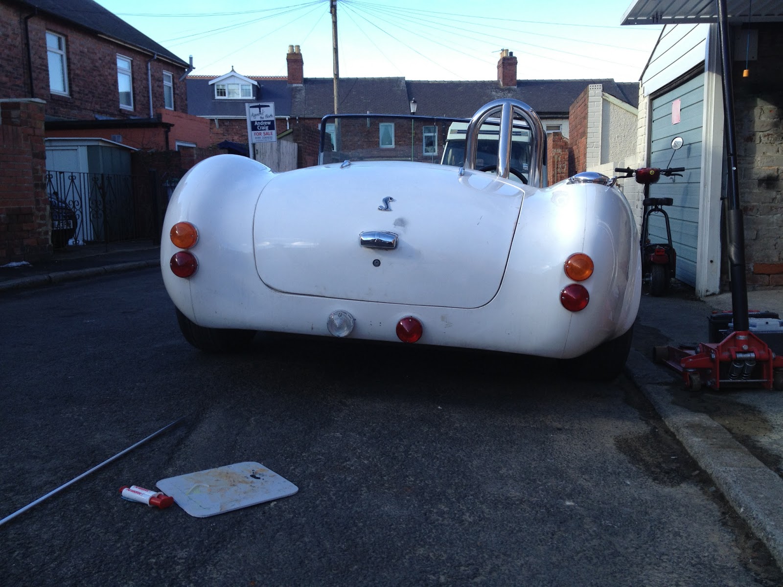
 The best solution for me was to fit a small bear claw lock to the inner skin of the boot that latches down to keep the boot closed. And opening is provided by a small glove box lock and key which is just wired to the claw latch on the inside. The picture above shows how it will work. I need to remove the boot and tidy up all the filler and smooth off some edges, but overall functionality is perfect and is now secure with a key.
 With the lock fitted it leaves me with a situation of how to mount the numberplate and leave access to the lock. I thought a couple of small spring hinges allowing the plate to hinge down from the bottom, but finding a suitable spring hinge was quite a challenge. Plenty of hinges about but they were all so bloody big and would have looked ridiculous.


I started a thread on the CobraClub forum regarding my lack of progress finding a suitable hinge, and was advised of a company in Holland that make spring return numberplate houses for fitting LPG conversions. It allowed an LPG filler to be mounted on the car and concealed with the numberplate. I ordered the said bracket which was a bit expensive at 50euros, but was essential to the build and offered a solution to the problem. When it arrived it looked perfect and was basic to fit. However upon a trial fit it stood far to proud of the back of the boot and looked a little weird, but the functionality was there and that was one good point. (the video below shows the initial fitting and you can see how weird it looks)

Some fetteling was required to allow the plate to sit flush with the boot skin, this was firstly achieved by removing two great rubber bump stops they were a good 8mm deep so that made a huge difference to start with. I have also bent the bracket slightly to follow the curve of the boot and this again looks 100 times better.


I still need to adjust the bracket on the pivot point just slightly to allow the bottom half of the plate to go further back but overall its starting to look acceptable and less of a bodge job.

I haven't had time today to do the bottom of the bracket, but its added to the list of little jobs to finish off. It shouldn't be to hard to do, just drill a couple of holes further back in the pivot lugs to bring the plate back a touch. Just 3-4mm would make a massive distance. Although the two rubber stop mounts have been removed i can just stick some thin protective pads to the bracket to stop any paint damage when finished..... if i ever get finished (fingers crossed for a lottery win)


The picture here shows how much better its fitting now than the initial fit in the video below. The numberplate was the only one i had to hand for a trail fit, I'm aiming to get a pre72 reg number that would be silver letters on black backing (i have to check legality's) this can then be printed on to the old fashioned tin plate and will be simple to mount on the bracket, once registered. The bracket itself is just held on with a couple of short bolts into rivnuts, so can be removed for IVA test which the bracket itself would fail due to radius edge, but ironically not when a numberplate is fitted.


Saturday, 2 March 2013

Fog on the Tyne!!!!

This update is dedicated to Mr Richard Dixon, who has been bitching my arse on facebook because my updates are few and far between... this one is for you Dicko you fuckwit!! ha ha

Before i start on the fog and reverse light, i though i would show you my knob, its very pleasing to hold in the hand, but my shaft is a little bent as you can see (so many puns available, but I'll leave it at that)  This was the style of gear knob i wanted from the start and this one was a eBay steal, and allot cheaper than retail cost. Wasn't an easy job to fit to be fair, firstly cut straight across the old gear selector then i had to grind down the diameter of the stub i had left to fit the internal diameter of the new gear selector. This is then held tight by 3/4 grub screws that hold it nice and tight. They also make removal fairly quick and easy as this gear selector is not IVA compliant.... bugger!! time to make another one for the test then!! I will hopefully find the correct rubber gear gator and chrome surround whilst hunting the internet for more parts.


So onto the fog light and reverse light. On my finished car i don't want the horizontal nudge bar that most people fit on their cars and they then fit the reverse and fog within that. I'm considering some nice quick quick jacks but again not IVA compliant so maby afterwards. This left me with a decision of how to mount the two lights, i certainly didn't want any brackets coming from under the rear valance and i didn't want to have to make bloody great swan neck brackets to fit them. I decided the best way was to have them surface mounted just off the centre line. This left me with another problem as the rear valance is contoured and curved so surface mounting isn't just a simple bolt on job. My first few attempts ended in failure, but you need to fail first in order to succeed (or so I'm told) I thought i could create a contoured flange the same diameter as the light unit, i had some bits of off cut drainpipe that was the correct thickness and diameter but i found it very tricky to get it cut to fit... so tricky that i said a few bad words and gave up on that one.

Idea 2 was to make a wedge of fibreglass body filler and sand and shape that to fit.This ended up the same fashion as idea 1.... lots of bad words and fingers covered in fibreglass bodge, so scrap that.

Idea 3 was the winner for me. I started by extending the length of the mounting threads on each light unit, simply knocked the old ones through opened the hole a little and in with a M6 x 100 bolt, you can also see two little brass nipples that take the lens holding screws. These i needed to bond into place from the back to stop them falling off when fitting the light, so a little epoxy glue and job done. I also bonded the rubber backing to the back of the light to stop that from looking unsightly from a side angle when fitted.

Now to measure and cut the rear skirt. Normal rules apply "measure twice... cut once" or measure ten times in my case. First is to cut the larger hole for the rear of the light unit to fit in. The light can then be offered up to mark the fixing bolt holes, i opened these a little to give some adjustment as they will be secured with a penny washer and nyloc nut from the other side. The reverse side is not integral to the boot, and sits just under the boot floor skin. This is good as it helps keep the lights high enough to be IVA happy as the bottom of the lens cannot be lower than 250mm from ground level.


Now i needed to make a spacer to stop the light from just falling down or just point to the floor. I used some alloy tube that was very easy to cut and shape with a file. This then just sleeves over the fixing bolts as the come out the back of each light and stops the light from pointing down to the ground. And yes the pictures here do show sunshine!!! it was almost an alien concept to be outside and not be balls deep in snow, or flood water. And the temperature was a tropical 8 degrees so i didn't take any risks and whacked on a load of suncream!!! ha ha


Once i had the little spacer sleeves done it was just a trial a error process on getting the correct angle to get the lights to sight right. The advantage to me with fitting the lights like this is their will be no damage to paint work when that's done, but the light will sit as far back to the body as possible, so the top of the light will be touching the body (12o'clock position) and the two bolts sleeved with the spacers and look nice and tidy.


The fog light in this picture is not an IVA happy one...something to do with parabolic reflectors or the like.... parabollox in my opinion. However these are the rules i must follow, so i will...... currently. LOL

The fog in this side picture does look to be pointing down, but its just the angle i took the photo and the uneven ground surface.


 I'm thinking that i don't like the way the centerline of sight is thrown off with having one clear lens and one red, so i might look into getting another clear lens and a coloured bulb, that way everything is kept uniform and pleasing to the eye. I could even just re wire the fog to be a second reverse light (with clear lens) then just fit the red fog for MOT time and switch the wires back over?? not sure yet.


So all sorted and happy with the work today. Another step closer and another job ticked off the list i have a few snag's i need to sort out but nothing worthy of a blog update. So keep your eyes peeled for more updates soon. (probs battery tray and kill switch next)


All tested and working fine. Good
 

Saturday, 23 February 2013

Fuel Filler Cap


I decided to treat myself to the Aston filler cap from Chris at Brasscraft along with the filler hose and clips etc from CBS. The filler flange that the Aston cap attaches to i had already got from Brasscraft last year. Allot of people do say that Chris's products are expensive (and i agree they are) but they certainly have a top class quality to them, and you would be hard pushed to find a better quality item, so worth the money in my opinion.

I intended to initially bond the filler flange to the body as so that no fixings were visible and kept with my "clean lines" theory that i was wanting to achieve. This plan sharp went out the window when the filler hose arrived. I ordered the heavy duty filler hose rather than the super flex stuff as i was trying to avoid fuel vapour smell in the boot once completed. However the heavy duty hose is so rigid that the amount of pressure it would put on the filler flange meant that it would never have bonded in a million years, so drill the flange and countersink the heads.


First job was to cut the access hole in the inner wing so the hose can pass from the cap to the tank. Not an enjoyable task to be honest, as the hose is very rigid so not easy to flex through the gap, and when cutting the hole i wanted it to fit nicely, rather than to big. Once the hole was cut it needs to be edged with some off cut of rubber bonnet seal. After paint and IVA i will seal round the gap with some silicon to stop the weather invading the boot area. I have also cut the hole big enough for the filler breather pipe which is just a length of 10mm fuel hose.


With the hose roughly cut to length its just a case of trial and error, until the correct length is achieved. You need to take care that you cover the filler of the tank as so to stop any crap or crud falling in as your working. I found it best to secure the top flange with the locking insert as so that end was sealed and then offer it down through the wing onto the tank. 


With the length pretty much done, now was time to drill and fit the top flange. Chris machines in the fixing positions equally around edge so its just a simple case of drilling through and then counter sinking the heads of the screws. When you get the filler cap you will also get some paper washer/gaskets that fit into the cap and will adjust the lock down position. So if you need to rotate the cap a bit you can just insert x amount of washers and it will reduce the amount of rotation before locking out. After checking with AK regarding this i was advised not to use any of the washers/gaskets so that the cap screws all the way down onto the flange. This is to do with the final height and orientation of the filler for IVA requirements. 


When it comes to the screw/bolt heads i ordered stainless steel socket heads so that they fit the recess nicely and fixing using an allen key. The only way i was able to cut the countersunk recess was with a larger drill bit then  to slowly open up with the dremmel. I do have a bit to do it but with the threads for the filler cap it would have made a terrible mess of the polished finish. Overall it looks ok, not perfect, but not noticeable unless you really look, and half the heads are covered when the cap is screwed down. So move on to fitting the flange to the body.


Before any cutting and drilling the cap needs to be screwed down and roughly put into position. You need to make sure that when the cap is open that it doesn't flip back and touch the bodywork, same with the release clip. This is something i hadn't even considered until i checked with Wendi at AK. Imagine getting the car all painted and then when you open the cap you chip the paint i would have been gutted!!


The cap needs to be rotated clockwise as much as possible before it touches the body on the hinge and release clip. Again this is to comply with the IVA regulations on radius i believe. I was speaking to a mate Paul the other day regarding this and i fear i will have to rotate mine more (i had already drilled and fixed) as he was saying that the cap hinge needs to be pointing towards the passenger side windscreen post in order to achieve the required angle for IVA compliance. Mine is more towards where the passenger side roll bar leg would be (if i had one) So something i will have to possible adjust prior to IVA. I'll keep you posted.

Fitting the flange is just a simple task of drilling through the body to fit. This is why it is important to finalise the position of the filler cap first with regards to it touching the body, as the fixing holes will obviously be in a required position. Also i was sure to cover the filler hose prior to drilling through the body as you don't want fibreglass dust down in the tank!! Also another tip i thought of when fitting, don't let your neighbour stand watching you next to an open fuel tank with his lit cigarette in hand!!! haha fuel vapour is allot more volatile than the liquid itself!! Just ask "Tony M" of the Cobraclub forum.... he has a great knowledge of fuel tank vapour and explosions!!!

So all fitted and complete you will see that the cap also has a locking insert which i have been told is not actually required for IVA as the Aston cap itself has a seal. I personal will just leave it in i think, its no hardship to undo when filling up, and will mean i have to remove the key from the ignition in order to fill up. I have also got a unleaded fuel restrictor in the cap, as so that if the diesel pump is picked up by mistake it will not fit the filler. I have never in my life miss fuel but i sure as hell don't want my Cobra to be the first time and my daily drive is diesel so "belts and braces" technique again. 


I'm happy with this overall and all that is left to do is to fit a one way valve to the breather hose to allow the tank to breath in the hot summer. This will just be running up the filler hose and secured above the fill level under the flange. I will also be running an earth cable from the filler cap down to the chassis, as so to reduce the risk of static spark when filling up, this will simply be a ring terminal off one of the fixing bolts down to chassis... job done!!!                                                                                                                             Next on the list.... save shed loads of money for wheels and tyres!!!! so expect an update in 2015!!

Monday, 14 January 2013

Clean the Screen


So another update on progress..... yes two updates within a month wowsers!!

After Christmas i also ordered the wiper package from AK this consists of the wiper arms and blades, wheel box's/spindles and the wiper motor complete with bundy tube. On the AK in order to achieve full clearance of the screen 3 wipers are needed. This is one of the first bits to look at to identify an AK kit. This was one of the bits that i was considering changing and only fitting two wipers simply because i prefer two to three. But after chatting to a few people i have decided to follow AK's advice and stick with three, this will give sufficient clearance of the screen required for IVA and not leave the centre part of the screen unwiped. So first things first when cutting into the body is measure twice and cut once. I simply laid the tapered chrome bezels on the top scuttle just in front of the rubber windscreen seal, to give me a rough layout of the position of the wheel box spindles. They come with rubber washers to protect the paintwork between the metal and the body so these are good for using as a cutting template.


Once i was happy with the spacing and i had checked the underside for clearance etc.. i checked all measurement's again. I even held a wiper arm and blade in position with each spindle position and checked roughly screen clearance and wipe area.

So with the areas to be cut marked out. cutting could be started, simply with a good size drill bit and position the drill so that it cuts through at roughly the same angel as the spindle will be (rather than just straight down through the scuttle) Once one was done its just a simple case of opening the hole slowly using a file so that the spindle of the wheel box fits through nicely, these are then just held in place with the top bezel and nut. now  repeat the process twice more and fit the wheel box's.


When the spindles are secured i was able to offer up a wiper arm and blade, and with no gear linkage in place its free to move so i could do a good check for the sweep. I didn't want the blades to catch the top of the screen or have any contact with each other during operation or parked position.

Same again with two wipers fitted, checking clearance and movement of the arms and same again with all three on. This is actually a very enjoyable job to do in my opinion, its very simple and with basic understanding of how this all operates its great to see the wipers move and do what they are supposed to do.


So now with all three wheel box's and wipers fitted its onto the motor itself. This is located on a pre mounted bracket on the AK chassis under the scuttle just to the right of the steering column. It is held in place with the supplied clamp and rubber mounting blocks to keep the motor nice and quiet when running. If you have any experience with classic mini's the wiper setup is exactly the same, but the motor is fitted in the engine bay rather than cockpit.


The wiper motor has a long geared cable (i forget its actual name) looks like a long flexible Archimedes screw that runs from out the motor. This is simply fed through the wheel boxes in turn and provides the movement for each wiper arm. I initially put all this together and did a quick test run. This was exciting pressed the stalk down and the wipers burst into life sweeping the screen very nicely indeed... happy days.


Now was just a quick case of fitting the bundy tube. This is just a alloy tube that has to be cut to size to fit between each wheel box so the geared cable runs through it. This is cut with a pipe cutter and when you have required length you will need to put a small flare on each end. This is so that each wheel box clamps over it when fully installed it actually firms up any movement you had in the spindle when just held with the top nut. A little bit of patience here as its cut then flare and test fit... if still to long, cut again another flare and test fit.


When you have all sections cut to size and they fit well its time to get down and dirty.... The bundy tube and all the gears will work best and more importantly quietest when they are well greased up. So i set about ramming each section of tube with as much bearing grease i could get in. Also smear the geared cable with as much as you can, nice messy job this so keep some cloths to hand.


Now were starting final assembly (well final for the time being, as a full removal will be required for paint shop) with all the box's linked and clamped, and the bundy tube all secure you can cut off the excess of the geared cable. I left a good 3"- 4" overhang to account for the movement when in operation and cut back. So with all this complete only one job left to do...... test they all work.


Working well as you can see in the video. Some bending of the arms is required to give a good even clean of the screen along with some grease in the arm springs, as you can hear in the video they are a little creaky.

I also sprayed the screen with a misting bottle to see how they preform, and i was pleasantly surprised. I was dreading they would be like one of my old mini's where a took a perfect working set of black plastic blades off and fitted chrome wipers.... only to find the looked nicer, but instead of wiping the screen they just smeared the water and made visibility worse, but they looked nicer than the black plastic ones..... so they stayed on!!!

I still need to drill a couple of holes for the washer jets bit this is just a quick 2 second job, so no hurry for that. 

Another update soon. I'm hoping to get a few loose ends finished off such as the fuel filler hose and filler cap, along with little jobs like the heater air flow to the matrix and the internal foot well vents. Keep checking back for that in the next month i hope.

Friday, 11 January 2013

Christmas gave me gas!!!!

Well did threaten an update soon, and now Christmas is in the past i have managed to find some garage time and get some bits done.

I placed an order with AK for the gas rams for the boot and bonnet, along with the windscreen wiper package (see next update)

Upon arrival i started with a quick dry run off all the parts that had arrived. After checking a couple of things with AK Jon advised me to do the bonnet first and boot second. This is because the gas rams that are sent are rock solid with gas and you have to bleed the gas out using a valve provided to give the correct resistance for the item being held. With the bonnet being heavier than the boot it makes sense to to this first in case too much gas is let out by mistake, it can then be used for the boot.

The bonnet setup is basically an right angle bracket (with a face of polished stainless steel, for strength and cosmetics) with the gas ram that then attaches to another U shaped bracket and then that to the rib's moulded into underside of the bonnet.

Its hard to show the bracket fitted on the inner wing, simply because its polished stainless steel and it just reflects the light, but this simply bolts through the inner wing with the mounting for the bottom of the gas ram protruding out under the rain channel. The bracket is fitted roughly 1" back of the chassis crossover. This is so that enough room is available for when the ram is in the closed position.

When the bracket is fitted its just a simple case of measuring back 11" along the water channel from the lower gas mount point and transfer that mark to the underside of the bonnet for the top mount plate.

These measurement's are important as they decide the amount of angle when the bonnet is open... in hindsight i would have adjusted slightly to give me a little more open angle, but its not going to worry me as its perfectly acceptable as it is now.


When fitting the top bracket AK say just to rivet in place. Now that's perfectly fine, but when it comes to getting it painted, i don't want to have to drill the heads off. And more importantly i don't want rivets loos in the bonnet rib, so that every time i lift the bonnet i can here them drop down the front. So i just simply marked the correct position and sunk in a couple of riv nuts, this then allows me to bolt the top bracket in place and undo when i want. No need to worry about masking off when the body goes to paint.... I'll just remove the gas rams totally.


Now once the top and bottom bracket are fitted the bonnet will hold itself up on its own!!! bye bye trusty piece of 2x2, i might have to frame that bit of timber its been so much use wheel chock, cut size for the windscreen rake, bonnet stay, boot stay and bits cut off to wedge the door latch plates.
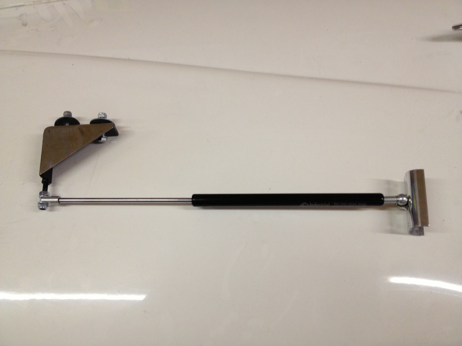
Now it comes to bleeding the gas rams... slowly slowly catch the monkey. So simply remove both rams (they now just unscrew from the mount plates) and with the valve provided remove a little gas at a time. Jon advised that with one ram on the bonnet its should have just enough gas to let the bonnet fall, as so when they are both fitted they will hold the bonnet without any issues.


I will admit now that i did balls up on one, i was letting out the gas and as i unscrewed the valve it drained all / 90% of the gas from the ram, so this has been relocated to the boot as it has a lesser load to deal with.

And with most progress on this car its a classic case of "two steps forward, one step back"

the gas rams have pushed the bonnet back so mush (in the closed position) that my bonnet lock cams are catching again on the water channel. So some more adjustment there along with the bonnet shut gaps. All part of the fun i suppose.

Another concern i have is that when the bonnet is closed the rams are both directly above the manifolds so they will be exposed to a massive amount of heat. I have seen a couple of posts on the CobraClub forum regarding this and failed struts, but i will cross that bridge if and when i get to it.

Garage time wouldn't be the same anymore without a visit from my little mate to have a good look at whats going on. Hes still a little scared when the engine gets fired up, but I'm sure he will learn to love it...... his dad certainly did!!!

I also believe that he could be made into a bonnet mascot as he would meet the IVA test with the 3mm radius?? not to sure about the visibility. Cheers for the help little mate!!!


So moving onto the boot. a little more thought here than just simple drill and mount like the front. The gas lower brackets need to be bonded to the underside of the rear wing. AK advise to just bond in with filler, which I'm sure is OK, But a fair amount of force is being held on these brackets, and to add with the continual use of the boot i don't want brackets to come loose in the future. So i wanted to add the "belts and braces" technique. This is simply just drilling through the water drain channel and the bracket and holding in place with a rivet.


The rivet you can see here in the water channel, but it will be practically unnoticeable when its been painted and the rubber boot seal is back on. And it will add some much needed strength to the bracket and not allow any movement which may start to de-bond it from under the wing.


Now onto the top brackets for the rams. Exactly the same principle as the bonnet here, again I'm using riv nuts to allow removal of the brackets come paint time. You can see in the picture the initial holes i have filled when i was experimenting with my internal boot hinges. This i suppose was lucky it was a failure as the fixings would have clashed with the mounting plate. But I'm still a little disappointed i couldn't get them to work..... maby on the next one!!??


So that's the boot rams fitted, another job ticked off the list. Overall I'm very happy with the fitting of them all. As you can see in the picture with the boot open that it is drooping a little on the right. This is because its the ram which i let all the gas out of by mistake... error.

Its not that noticeable and i did make enquiry's with the manufacturers regarding re-gassing, They have a small cost of £5 to re-gas's...... and £16 courier as its compressed nitrogen. So that can be added to a snags list after completion of the car.