Welcome to my Blog. Over the next couple of years i will be updating and showing you all the progress of my AK 427 Cobra build. You will be able to track my progress building a lightweight sportscar with monster V8 power, stunning good looks and alot of hard work and determination.
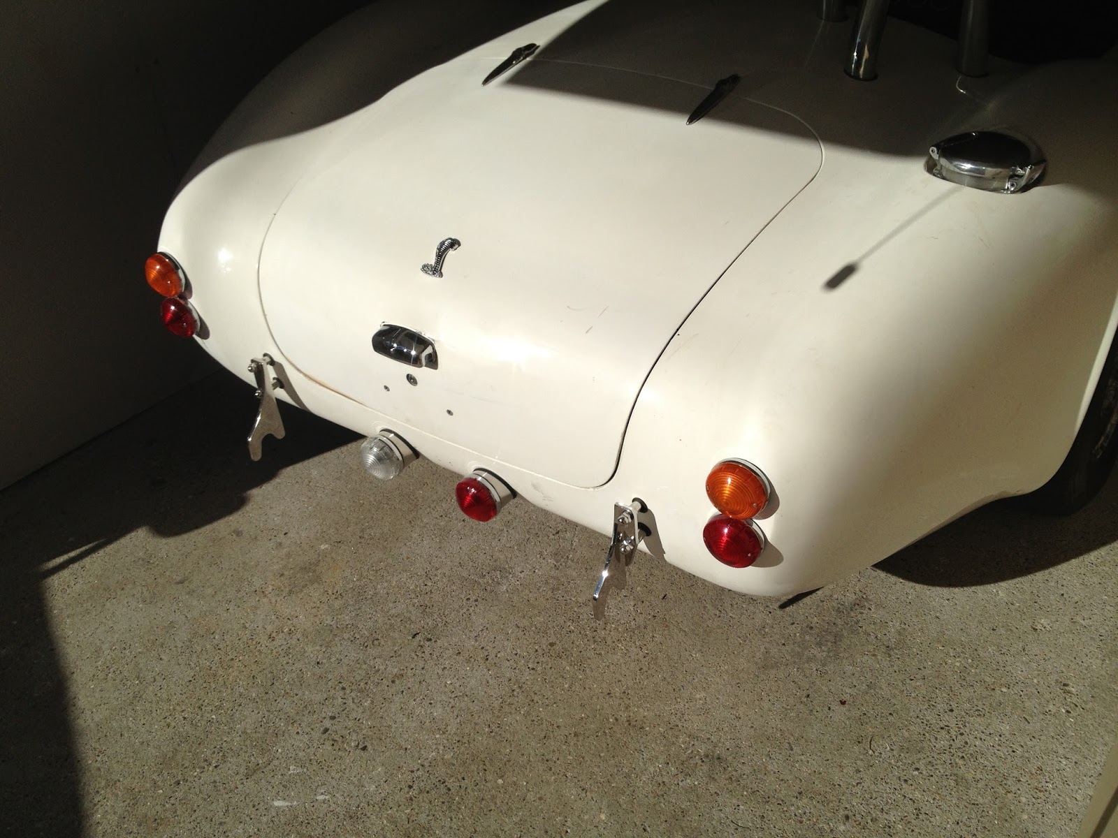
Just another little update for your Cobra lovers of the world, this time I'm doing the rear reflectors, which are a legal requirement for IVA test and future MOT tests.
Initially i didn't want permanent reflectors on the car, I was just going to get some little sick on ones that would have been IVA compliant for the test, and I'm sure they would have fallen off at some point on the return journey home, but re-attached them self's for the MOT years down the line.
My reasoning for this was because i didn't want the back end of the car to look to cluttered/busy or have to much going on.... Less is more for me.
However with my recent addition with the stand offs for the fog and reverse light i was on the prowl for some similar style reflectors. I cant really remember where i initially got the idea for these ones, i think it was my brother in laws new motor when i saw that. They are the rear reflectors off a Mitsubishi L200 and similar to the fog/reverse stand offs they are contoured to the rear of the bumper and thus fit the rear of the Cobra very well also.
I managed to get a pair brand new through eBay for less than £10 so like most bits lately, not exactly massive expense for a part that looks correct and less of an afterthought. They are fitted with a single bolt through the centre of the unit, which you just clamp into position with a nut. You can see on the picture the little hole in the rubber which is where they had a little locating lug for each one (offside and nearside) this i just simply cut back as i don't want to cut more holes in the body than i needed to, I presume the bumper of the L200 has a recess for these to slip into.
Next up was to measure a thousand times and drill a mounting hole. I mocked them up first with blue tack to get a good position and play around with the location of them. The IVA does have specific rules regarding the position of these reflectors. Basically in a nutshell they can be fitted anywhere on the rear of the car so long as they are red in colour, mounted lower than 900mm above ground level and above 250mm ground level along with within 400mm from the edge of the car. I tick all of these boxes with my final position so these should not fall foul of any IVA testers checks. But there is also no limit to how many reflectors are fitted so if for any reason that these cause issues i can just use some stick on ones for the test not that i should need to.
You can see now with this picture of the back end about what i mean about it getting cluttered and busy, lots going on and looks a little uneven with the red of the fog and the clear of the reverse. This will be solved by the use of an red LED bulb for the fog light, but with a clear lens on so it should balance it out a little.
With this close up shot you can see how they mimic the fitting of the fog/reverse, so keeping the theme at the back and looking like a professional fitting unit.
This will all get tied together nicely with the final body colour and the stripes... when i finally get that sorted.
I'll end this update like I've ended my last few.... Still saving for bigger bits, feel free to send donations.
Another little update for those that are following my progress. After travelling down to Silverstone for the classic event back in July i had seen again up close the mounts that GD make for the rear fog and reverse light. It got me thinking more about mine and how piss poor they were basically. Mine looked more like an afterthought currently with them just stuck on the rear valance with no visible mounts or support.
So back towards the end of August i sent GD an email requesting an order for a set, i was pleasantly surprised when after a week or so i had a reply (they were on holiday so office was closed) For those not to knowledgeable about the kit car market, some manufacturers are strict on what they sell to who. I wont go into name calling but its the same logic as some BMW's, as in you have to supply a chassis/reg number to order parts and only then will the manufacturer sell you the parts, once they are happy your not trying to pull a fast one or fit parts to a non branded car. Either way I'm glad to say GD are not like this whatsoever, a sale is a sale and no sooner had i received the invoice, i made payment and they were dispatched within a day. So thumbs up for GD from me, the quality of the stand off mounts is superb and they fit like a glove... happy happy me.
I don't think i need to go into to much detail on how they fit, its fairly straightforward. Just remove the lens and two long bolts through the lamp unit, through the stand offs and through the rear valance, held in place with two washers and nuts. Re-fit the lens and job done. Lucky for me the mounting holes i had previously cut in the rear valance were perfect location for the replacement stand offs..... so it must have been fate!!
The car is really starting to come together now, and its desperately needing some cash thrown at it to get it all finished. Hopefully the plan is to get wheels and tyres just before Christmas (£2000-£2500) then paint just after Christmas (£3000-£4000) the interior trimmed and fitted around Feb/March (£1000 - £1500) and then the IVA test soon after that...... fingers crossed for next summer (back end of summer) on the road and legal.... but please don't hold me to this ;-)
Hello again Cobra blog readers. Firstly thanks for you for your patience for what seems like a huge gap since the last update, to quote my mate Ian Cogden "life has got in the way" i have took on another day job which sees me working even further hours and along with my little mates 3rd birthday, spare time and energy has been very very thin on the ground.
So to kick of this update I'll summarise my twin cooling fans install. I have always loved the look of the front twin fans, and followers of my progress will recall i have a thermostat controlled puller fan behind the radiator. So this is the "belts and braces" part of my cooling system. I'm putting two classic style fans in the front nose that will be switch controlled, so if I'm stuck in traffic or start running hot, then i have some additional cooling available at the flick of a switch..... i so i hope!!
So firstly i needed the motors. Many options are available (mostly cheep Chinese motors) but the big beefy ones off an MGB were what i opted for. These are actually fairly hard to get hold off new, but i dropped on with eBay and managed to pick up two for a total of £60. Most MG suppliers list the motors in their parts, but the availability was poor through all the suppliers i contacted.
I had picked up a couple of 30 year old fan motors from a MG breakers yard but they were past their best and the bearings were shot (however the mounting brackets came in use) The motors i got had an 8mm spindle shaft for attaching the hub/fan, i believe the original MG motors also have a 8mm hub, with grub screw thread. They are 12v DC with just over 3000 rpm.
Next on the list was the fans themselves. These are just of an industrial fridge/freezer. I picked up a couple of 250mm fans for less than £10 including postage from an fridge repair website. The fans i got were just pressed alloy with no hubs or fixings attached. This did become a little obstacle to overcome, as i found getting a suitable hub a little bit of a challenge.And after a couple of experiments with odds and sods i had lying around it ended in failure. I then, after google searching everything i could think of, came across a robotics website that listed a robotic wheel hub for a 8mm motor shaft and at £3 each they were hardly expensive. I had just been speaking to Lee that day (the original inspiration for these fans, off the Cobra forum) who informed me that you could get the fans with the hubs already fitted, but with these in the post i thought i would give them a bash. When they arrived i was very pleased with the quality of them and the engineering in them for the price. They have a perfect 8mm centre, secured with a nice allen bolt, and 6 equidistant holes for the fitting of a wheel.... or fan in my case. These were just simply drilled through into the fan and held in place with some little M4 nuts and bolts (all with a little locktight for extra security)
As you can see in the picture, it all went together fairly nicely and more importantly well balanced. you cant have these spinning round at over 3000rpm an inch away from your radiator without them being balanced, they would just shake themselves apart otherwise. Once the two motors and fans were fitted the obligatory "bench test" was carried out and the torque from the motors was very very impressive, along with the amount of air they were pushing, more than sufficient for additional cooling. In fact i believe Lee was using his as his primary cooling system controlled through a thermostat but again that would be more than sufficient.
So with the motors and fans ticked off the list, next up was the fixing bracket. This is simply just a length of box section, with angle brackets either end, and with the original MG style motor clamps bolted on. I say "simply" but all this takes time of measuring and cutting, measuring again, trail fit and then spacing of the brackets with the motors and fans fitted. The whole bracket is then fitted into the nose at the desired angle and height and secured with some bolts through the inner wing which is 5mm thick fibreglass with the stainless steel cladding, so certainly strong enough.
So now a trial fit of everything, and when i stood back to have a look i was very very pleased with how they looked. And with it all in place another quick test run with a battery back to see how they worked... again very very pleased. So stripped it all back out again, so i could give the bracket a good coat of chassis black Por15 (which is the same tin i purchased back when i did the Jag parts refurb.....cripes that was a long time ago)
Once everything was back together and installed on the car, it was time to route the wires and fit the dash switch. If you have followed my blog you may recall that i fitted an additional fuse box specifically for bits like this which were planned at some point during the build, and I'm glad i did. So not too challenging to feed some 27amp wire along from the motors to a 24amp toggle switch hidden behind the wiper control stalk (within the IVA dash exempt area) then with a 20amp fuse it was ready to test. Fitting of all these wires and the routing all takes its time and in fact i spent more time doing bits like that then on the initial install of the bracket with motors. But if a jobs worth doing, its worth doing well.
So i suppose you would like to see how they work??? well watch this video and you will see. The frame rate of the video gives the appearance the fans spin in opposite directions, but in reality they spin allot faster than it looks and both anti-clockwise.
Well I'd been putting it off for a long time as it was not going to be
an enjoyable task, and if you are reading this and building an AK
yourself, then take this as warning!! Before the fitting of the body
(whilst it sat in my garden for a year or so) would have been a perfect
time to sit in the engine bay and paint all the inside of the fibreglass
tub. However it didn't get done and i was left with the fiddly task of
making it all look better than just a glass resin finish. What makes this worse is that i have the stainless steel cladding so this in turn reflects the underside of the wings, and looks horrible if not painted.
This task is made allot harder in my case as i had fitted the side pipes, brake servo, clutch master etc... and all the brake/clutch lines. I had to remove the exhausts and cover as much of the blingy bits as possible as so they didn't get speckles of paint on them. Then on with the laborious task of painting the inside. I used what i had left of the donor parts Por-15 chassis black paint, and it went on fairly well. I started of with a paint brush (stolen from the bairns painting kit) then for the larger areas i used a small roller that is designed for painting behind your radiators in the house.
As you can see on the picture the stainless cladding makes the underside look nasty and if you can picture a dark body colour on the outside, if i had left this as is it would have look terrible. It was one of those jobs that i hated doing, but was just a case of start at the start and crack on. Now its all done I'm much happier and it looks instantly better IMO when you open the bonnet. One issue i did have whilst doing this task was the amount of swarf i had on the floor. This got stuck in my head and as i stood up went down my neck, and then down into my arse crack basically.... iv never had swarf in my bum before, and i hope never to have it again. Lesson learnt, tidy up after myself.
Ignoring the dust all over the cladding you can see what a difference it makes to get it done. The paint finish isn't perfect, but when the final body colour goes on top, this will also help block the sun light penetrating through the thin bits and not be so eye catching.
Next on the list was heat protection. Whilst at Stoneleigh show i was keen to see what heat protection people had chosen to protect the brake servo, brake lines and clutch. Some had fitted a plate between the bulkhead and the back of the inner arch but the distance between the slip fit of the exhaust and brake servo is only about 1" so space was tight.
One solution that did stand out to me and looked cosmetically appealing also, was a bonded woven reflective tape. Similar to your standard exhaust wrapping but with a reflective side. I didn't want to wrap the exhausts as i have seen the damage done to the exhausts when this stuff is left on for long periods of time, and so that was not an option for me. But this reflective protection is bonded onto the brake servo and whatever else you want to protect. MattS who lives near my parents in Stratford upon Avon had done a lovely job with his heat protection and it was from this that i took my inspiration. More importantly he had just got his Cobra legal and on the road, so this form of heat protection was IVA friendly. Matt acquired his reflective tape from his employer (Jaguar) and so i was on the look out for a similar product.
I soon found some stuff that was very similar, it was a woven ceramic with one reflective side and adhesive bond on the other. With the exhaust side pipe still removed to ease access it was cut into strips and applied to all the areas needed. Another key area to protect is the brake light switch (pictured top right of the photo) these have a habit of failing early if not protected from excessive heat. It all went on very nicely and looks neat when looking from through the open bonnet. I wrapped the short run of brake lines also that run beside the back of the inner arch, and i had enough excess left over to protect the starter motor also.
Whilst i was on a productive roll i decided to re-route my clutch line and some of the loom also. I was never happy with how i had the clutch line coming in from right beside the fuel pump, so i manged to get a better route (haven't pictured) where it comes directly up from the offside cross member and along the top of the inner wing (behind the bonnet water channel) and then into the master cylinder. This looked so much better instantly and keep the engine bay looking tidy and less messy.
So next progress will be same as last time, just saving for big expensive bits. But these little odd jobs are good to be getting ticked off the list and getting finished off.
Well another job ticked off the list with the fitting of the quick jacks. These are cosmetic only and will be fitted post IVA as i don't want to take the risk of them failing the radius or sphere test. Lots of Cobras have them fitted for a period look to the cars and they really finish the front and back end nicely in my opinion. They replace the nudge bars and overiders and just generally look nicer keeping the car looking smooth and less cluttered.
Quick Jacks are basically two brackets fitted front and back and back in the vintage racing days they would be used to jack the car up for service or tyre change. They are purely cosmetic in my case as they are only bracket mounted onto the body (which is fibreglass) so they would never have the strength to support the car.
I purchased mine from Chris at Brasscraft and lets say i didn't see much change from £250 for a set of 4 brackets, 2 x 10mm bar, 2 x stainless steel tubing and 8 x dome nuts. However like everything i have had from Chris so far they do have a quality feel to them. They are made from 8mm stainless steel with a high polish finish.... naturally.
So pictured above you can see one jack with a section of 10mm studding and stainless steel tubing. These need to be cut to your required length and fitted to the car via its bracket. AK supply with the chassis two front mounting brackets, simply just a section of right angle steel and in my fitting (front first) i just cut some studding to a rough length so that i could make a final fitting component (pictured right) then i could provisionally start making some holes in the body for fitting. I deviated from suggested fitting slightly by putting a M10 nut either side of the cover tubing as so the mounting bracket and quick jack would then be torqued up to them rather than the tubing itself.
So with a one fitting made up i started to make some holes in the body tub. The front jacks are fitted to the inner wing via the AK supplied bracket. The inner wing is just roughly 6-8mm of fibreglass with a 1-2mm stainless steel sheet cladding, so you can see why these would not be structurally sound for lifting the car. AK did provisionally make some markings for the holes but mine were long gone so it was down to careful measurement and cutting slowly then opening each hole with a file for a better fit. The trick i found was to remove the lower studding and tubing of the bracket and just concentrate on the top one. Then when this was done i could adjust the rotation of the jack so that it sat vertical and true to eye and not cock-eyed. Although the body tub looks all symmetrical you will find that nothing is 100% accurate and that a large tolerance can be needed if measuring direct off the centre line.
So with one provisional fitted i took it all out again and cut more 10mm stud and tubing to match for the other side. Fitting the other side again is the same as the first but lots of attention to making the first cut into the body as they need to sit level either side and look good. Some adjustment can be had from drilling the hole's in the bracket oversize 12mm for 10mm studding that then gives a little adjustment all round for a perfect fit (Another reason to add the additional M10 nut as so you can secure the studding in the correct position)
To finish the fitting and to save the body from damage after painting, you need to fit some rubber grommets onto the body to surround the stainless tubing. These can be tricky to find and i was advised of some available from America for a pricey sum. But with my brain in overdrive and a quick rummage around and i found a number of 25mm grommets for electrical cable boxes (pictured below) these cost just penny's from DIY stores and fit perfectly. They can be cut and shortened to fit the diameter of the tubing perfectly and then give a superb neat finish to the jacks without any stress to the body.
Better still for me is you can these grommets with a blanking cover
(semi blind cable grommets) and these will be spot on for IVA as they
will fit the body perfectly and leave a smooth finish thus be IVA
friendly.
Moving onto the back brackets and fitting is exactly the same as the front, with one difference. The mounting bracket is bonded into the body tub so this just needs to be drilled through for the studding. On the off side this provides a good place for the earth point for the battery also.
The rear jacks need much shorter studding. However how far proud of the body they sit is personal preference when fitting, along with if they are fitted left hand or right hand offset. I just goggle image some pictures and went with what i though looked best.
As you can see the rubber grommets fit the holes lovely, all i did was thin out the fibreglass slightly to create a lip for them to sit in and job done.
So the back end looks almost finished now with the exception of paint and numberplate. I'm revising my boot lock idea again, and hopefully will have some updates on that within the next month or so. So still saving for wheels and tyres, paint and interior... donations welcome!!
Started tackling some long overdue bodywork prep. I'm just making a start on it really, i intend to leave most of the fine tuning for the body shop, such as door/boot/bonnet gaps. However removing the flash lines from the mold is a simple task so long as you don't take too much off and then leave a flat spot. So just long a tedious work with fine abrasive paper to take the bulk of them down. Another good reason to be fitting the interior and carpet after paint is because of the dust, fibreglass and gel coat creates an epic amount of dust and mess, so if this is all completed prior to interior fit it will save work later on i hope. After all logic says black carpet and lots of white dust isn't a good combination regardless of how care full you are.
Another little job was to fit the battery tray and cut-off switch. I ordered the tray from AK which is a nice well thought out bit of kit, worth the £40 it cost. Its clamps the battery nicely and fits the area perfectly. I'm fitting it in the standard position in the rear offside of the boot. It will all be trimmed and boxed out neatly but again after the paint has been done.
The battery all fitted nicely in the corner and final adjustment for the
battery clamps. I have fitted a battery cut off switch which will help
eliminate battery drain over the winter period along with it being a
safety feature if i need to kill the power quickly. I need to create a
better earth point for the battery, as its currently on one of the body
securing bolts, but i will change this to one of the quick jack
positions next month (when i fit the quick jacks)
I have also fitted a full alarm and immobiliser which is IVA compliant. I'm obviously not going to go into to much detail regarding this, as its the main form of security for the car, but its remote fob activated so no touching of decoders to dash mounted switches prior to engine start. Nothing wrong with that style, but i just don't like them and look unsightly on the dashboard. The advantage to mine being remote operated is that it offers a boot release signal for boot solenoid, and security for the doors and bonnet. I have had to fit the door switches that run to the earth and the bonnet switch also. This will double up as the foot well lights switch when i fit them (probs after the car is legal and on the road)
As many builders will agree, if you start making changes, you make further work for yourself as you have to start thinking one step ahead for the final product. No big issue in this case, but where i have fitted the door switches they would rub on the inner face of the door when in operation. If this was just left as paint finish it would be rubbed off within no time. So the solution is just a couple of little protective alloy strips that can be held in place with a rivet. They have been added to the "fitted after paint" bag, as i don't want to drill the rivet out and have it rattling inside the void of the door. I have pre drilled the holes mind so its a simple 2 second job to finally fit.
Also little jobs like painting the door hinges have been done. Can't have these as raw metal once the body's painted, would look terrible. This did involve removing the door, but the advantage of that being that i can check when refitting that the alignment is ok for the door catches and panel gaps. I was pleasantly surprised that all was fine so long as attention was paid to the fixing point when removing then re-fitting.
When i ordered the battery tray from AK i also asked about the door hinge escutcheon plates. These will fit around the hole in the body for the hinge and finish of that area nicely. Polished stainless steel naturally, but after a quick trial fit there is some adjustment needed to the bottom plate.
As you can see the top will be fine, it will just be held in place with a rivet either side (again fitted after paint) and the excess area within the plate, just trimmed back. However the bottom plate looks too big. I have emailed AK regarding this and awaiting a response. Its either a case of trim the plate to fit, but this will make it into two pieces and might look daft? or another slightly shorter plate to be made. It could be that i have just been sent four top plates as opposed to two top and two bottom. As it is currently it sits far to proud of the door gap and would void with the door when open and closed. However no major issue to sort it, I'll keep you all posted as i get closer to fitting them.
Next month sees the first show of the season for me, Stoneleigh kit car show. I have ordered some quick jacks from Chris @ Brasscraft and when i fit them that should be the final cutting of the body prior to paint.... So another update mid next month hopefully.
I still need vasts amounts of cash for wheels/tyres and paint, so donations welcome!!!!
Well another productive day today in the garage. First on the list was to finish of the bonnet locks. I've been meaning to do this for a while, but with the onslaught of more snow and negative temperatures still in mid march, i had not been keen to get back in the garage. However this required a couple of brackets to be made up to give the cams something to hold on to rather than just the fibreglass of the rain channel. These were easily made out of an off cut of strip alloy i had lying around. A simple 90 degree bend and a couple of mounting holes for some rivet's and job was done... now onto the cams and locks.
If you have been following my progress you might remember the initial fitting of the bonnet locks was too far back so that when in the open position the back of the cams caught the rubber bonnet seal when the bonnet was open. I did initially remove them fill the holes, re-position and fit which was fine up until the fitting of the gas rams. They pushed the bonnet a little with the pressure from them and made them catch again (but only by 2mm or so)
This time rather than fill the hole and move the handles again (weakening the fibreglass further) it made better sense to grind the backs of the cams down a little and shorten the then protruding grub screw to sit flush with the back of the cams. This has given me more than enough clearance and the bonnet opening is as it should be, silky smooth and proper job. With the cams fixed i could cut short the bar and give a neat finish. I'll look into making some finishing plates to fit around the bonnet rib to hide the tops of the cams/bottom of the lock. That will look very smart, and give a better look to the finish when the bonnet is open.
On to the feature presentation of this update. I have since day one, had an idea in my head regarding the boot lock of the car. With the AK kit the space between the bottom of the number plate light housing and the lower lip of the boot is marginal. And when the rear number plate is fitted you (on most AK's that i had seen) had to cut into the bottom of the number plate to allow the boot handle to be mounted to the boot lid.
I was more than happy to do away with the boot handle altogether, but this left me with a problem of how to lock/unlock the boot. The first plan was a electric solenoid to pop a catch from inside. This would have been fine, but security was an issue. I don't have a glove box so i had no secure place to have the switch. It cant be in plane view as the car is then not secure in the slightest. Also with the car potential hibernating through the winter (all 364 days of it) their is a risk that the battery could go flat and then i wouldn't be able to open the boot. I could have concealed some croc clips in the wheel arch to stick a battery on if this happened and pop the boot that way, but again security issue and not very practical. The battery going flat is probably not going to happen.... but if it did = Mr Cockup paying a visit.
The best solution for me was to fit a small bear claw lock to the inner skin of the boot that latches down to keep the boot closed. And opening is provided by a small glove box lock and key which is just wired to the claw latch on the inside. The picture above shows how it will work. I need to remove the boot and tidy up all the filler and smooth off some edges, but overall functionality is perfect and is now secure with a key.
With the lock fitted it leaves me with a situation of how to mount the numberplate and leave access to the lock. I thought a couple of small spring hinges allowing the plate to hinge down from the bottom, but finding a suitable spring hinge was quite a challenge. Plenty of hinges about but they were all so bloody big and would have looked ridiculous.
I started a thread on the CobraClub forum regarding my lack of progress finding a suitable hinge, and was advised of a company in Holland that make spring return numberplate houses for fitting LPG conversions. It allowed an LPG filler to be mounted on the car and concealed with the numberplate. I ordered the said bracket which was a bit expensive at 50euros, but was essential to the build and offered a solution to the problem. When it arrived it looked perfect and was basic to fit. However upon a trial fit it stood far to proud of the back of the boot and looked a little weird, but the functionality was there and that was one good point. (the video below shows the initial fitting and you can see how weird it looks)
Some fetteling was required to allow the plate to sit flush with the boot skin, this was firstly achieved by removing two great rubber bump stops they were a good 8mm deep so that made a huge difference to start with. I have also bent the bracket slightly to follow the curve of the boot and this again looks 100 times better.
I still need to adjust the bracket on the pivot point just slightly to allow the bottom half of the plate to go further back but overall its starting to look acceptable and less of a bodge job.
I haven't had time today to do the bottom of the bracket, but its added to the list of little jobs to finish off. It shouldn't be to hard to do, just drill a couple of holes further back in the pivot lugs to bring the plate back a touch. Just 3-4mm would make a massive distance. Although the two rubber stop mounts have been removed i can just stick some thin protective pads to the bracket to stop any paint damage when finished..... if i ever get finished (fingers crossed for a lottery win)
The picture here shows how much better its fitting now than the initial fit in the video below. The numberplate was the only one i had to hand for a trail fit, I'm aiming to get a pre72 reg number that would be silver letters on black backing (i have to check legality's) this can then be printed on to the old fashioned tin plate and will be simple to mount on the bracket, once registered. The bracket itself is just held on with a couple of short bolts into rivnuts, so can be removed for IVA test which the bracket itself would fail due to radius edge, but ironically not when a numberplate is fitted.